If you are a genuine music lover or a DJ that performs at outdoor events and big concerts, you must be seeking something that can play the deepest basses on such a massive scale.
This can only be achieved by a lab horn subwoofer. Tom Danley provided the conceptual idea for these subwoofers as the first DIY lab horn subwoofer.
And if you want to make one by yourself, this is the article for you.
The LAB Sub, also known as the LAB Horn, is a heavyweight subwoofer designed to operate as four enclosures strapped together in a 2 multiply by 2 “cube” arrangement to increase effective mouth size and generate a low frequency of 32 Hz.
These subs are thought to be the largest subwoofers ever manufactured in terms of size and sound. So, Keep reading to know more about lab horns.
What Are Lab Horn Subwoofers?
Tom Danley created these subwoofers; in fact, he never built one personally; he created the conceptual design, which was freely distributed to the public, and proved to be influential as the first DIY lab horn subwoofer.
It is a heavy subwoofer designed to operate as four enclosures strapped together in a 2*2 “cube” arrangement, increasing the effective mouth size and achieving a low frequency of 32 Hz.
The Lab Sub is designed to play in groups of four from 80 Hz to 28 Hz. It is not intended to play above 80 Hz, so it has very little output above 85 Hz.
Danley designed a 45-inch* 45-inch*22.5-inch (114 cm 57.1 cm) bivalves folded-horn subwoofer with two 12-inch drivers at the horn throat.
Eminence, an American speaker business, created a unique 12-inch driver called the LAB12 to match the requirements.
Has Anyone Actually Built A Lab Horn Subwoofer?

Since the LAB horn is a do-it-yourself project, it’s not surprising that there are at least five different versions of Tom Danley’s baby. We shall investigate each of them individually.
Version 1:
The first version, dated 2/17/02, was drawn by Tom himself, but he didn’t actually make it; instead, he provided the conceptual design and sketches for someone else to build.
Version 2:
Then there’s the second version, created by Brian Fehrman and accepted by Tom, in which the sub is built. It is much more complete and professionally done. It is dated 4/4/02 and was used to construct the first LAB horns ever recorded.
While there are various modifications from Tom’s original design, none of them create a significant difference in the horn flare.
We were all in the “horn learning” stage at the time, and several people noted differences between the two versions and the table of the “ideal” horn.
Some even believed that the difference between 3/4″ and 18mm plywood had to be resolved.
During this phase, Peter Sylvester made a third LAB horn version with dados and biscuits that “fixed” both Brian’s and Tom’s versions.
Version 3:
Peter built one LAB horn, then made more “corrections” and built another. According to Peter, there was no noticeable difference between his cabinets and the results reported by Al Limberg, “Too Tall,” and others.
While he may not have “improved” anything that was important in terms of acoustics, Peter’s version is the most durable box you could make.
Version 4:
Jeremy Bridges’ version was a flop since his drawing includes too many flaws for someone who lacks the experience to spot them.
It claims to be a “metric” version. However, the key dimensions are in English (but sometimes rounded to the nearest inch).
While the majority of the drawing is done in the usual third-angle projection used in the United States, Jeremy illustrated one area of the nose flare in the “Dutch” projection (first-angle). A couple of lines that should be dotted are not (horizontal flare #1).
Version 5:
Brad Litz’s version 3 is a significant revision. His version is intended for home theater use.
The sacrifices he made may make his version unusable for pro sound, making it more like fine furniture than a “roadie proof” speaker.
For example, he increased the compression ratio to 3, putting strain on the speaker cone. We won’t know if the LAB-12 can withstand the stress until this version is built and tested.
He has released 3-D cad files as well as some detailed part drawings on his website, so you must have 3-D cad to access the information. He utilized Horn’s response to model the adjustments and seemed to be pleased with the results.
Tom’s design is a complete success. All of the builders’ “improvements” did little to harm this tough horn. One or two-piece baffle, 3/4″ or 18mm plywood, 5 1/2″ or 8″ corner brace, various access covers, all horns worked perfectly.
Along with them, several individuals attempted and succeeded in making lab horns from Danley’s drawings. This can be simple if you have some experience cutting and combining wood.
What Is The Functioning Of A Lab Horn Subwoofer?
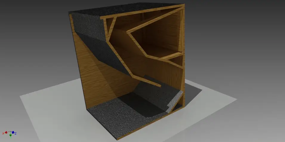
The lab horn or folded horn subwoofer design is an example of a standard horn design. The primary function of a horn is to improve the efficiency of a speaker.
As a child, you may have tried folding a piece of paper into a cone shape and shouting through it to make it sound louder.
This is a basic example of a real-life horn. Other, more practical examples are the trumpet and trombone. Because the horns are of suitable size, they are easily produced for high and mid frequencies.
As you decrease the frequency, the wavelength expands, as does the size of your horn. Here’s where the lab horn subwoofer comes in.
Folding the horn makes better use of space, making the enclosure more manageable in size. A genuine case would be the tuba, which is a low-pitched brass instrument. It employs a horn, but not a traditional one like the trumpet.
The tuba’s horn is not straight; instead, it is shaped like a snail to maximize space. A horn loudspeaker is intended to move from a small to a huge opening.
You can fold it or make it straight, but the idea must remain the same.
How Can A Lab Horn Subwoofer Improve Sound Amplification?
Impedance matching is the fundamental principle upon which the horn is based. The speaker is a mechanical system with a high impedance, whereas air has a low impedance.
When a wave traveling through a tube encounters a rapid change in acoustic impedance, some of its energy is reflected back.
Tubes are not something that horns are. They have a distinct taper. The cross-section of the duct or tube grows gradually larger. The horns function as an impedance transformer as a result of their taper or flare.
The transition takes place smoothly from the high impedance of the cone to the low impedance of the air.
As we’ve learned the basics of how the lab horn works, let’s go over the reasons why you’d want to connect a horn to your speaker:
- Significantly increased efficiency.
- Removing the resonance caused by speaker boxes.
- Directivity is increased. The sound does not extend as widely as it would with conventional radiating speakers. The sound is directed into specific locations depending on how the horn is created. Depending on the application, this might be a good or a terrible thing.
- Nonlinear distortion is produced as a result of speaker reduction.
Lab Horn Subwoofer Components
The horn is made up of three major parts:
- The throat is the part of the body that is connected to the speaker.
- The length of the horn is described by the neck.
- The mouth, often known as the bell, refers to the end of the horn that is “attached” to the air.
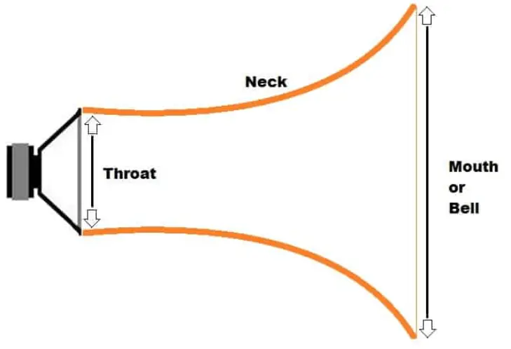
A horn will begin to expand from the throat and end at the mouth. The speaker will be linked at the horn’s throat and will emit sound at the horn’s mouth.
All of these components have an impact on how the horn influences the overall sound. The flare and mouth design, as well as the phase and direction of particle velocity at the mouth, will all have an effect on the horn’s sound quality and directivity.
The form of the horn is one of its most distinguishing features. The taper of the horn is determined by the cross-section expansion rate.
The cross-section area varies as a function of distance from the horn’s throat along its axis.
This function will give the horn’s neck a specific shape. This means that the neck can have a variety of shapes, although there are a few that are more frequent.
Lab Horn Profiles
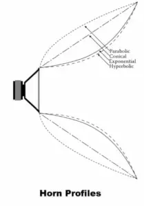
- Parabolic: Simple to develop and construct, but poor impedance conversion.
- Conical: Simple to develop and construct, but poor impedance conversion.
- Exponential: Good impedance conversion across a wide band, but some non-linearity.
- Hyperbolic: Excellent impedance conversion but relative non-linearity.
- Stepped: Conversion of high impedance. The step resolution determines non-linearity. This shape is distinct from the others. The horn does not expand in a fluid manner but rather in sharp square increments. These cubes are being played by the speaker.)
Things To Look For When Designing A Lab Horn
The major things to look for when designing a lab horn are:
- The function of transfer
- Nonlinear distortion
- The acoustic impedance at the throat
Other concerns include directivity, phase distortion, and resonance characteristics, but these are minor. Changing the length of the horn and the shape of the mouth can change the latter qualities. Conical and parabolic-shaped horns are less common as a result of this.
Exponential horn profiles, on the other hand, are particularly popular due to their high bandwidth, minimal linear distortion, and appropriate throat impedance characteristics.
When compared to exponential expansion, the hyperbolic expansion provides a response down to a lower frequency value, but the fall-off below that frequency is steeper.
Furthermore, because the expansion from the throat to the mouth is slow, pressure builds up inside and can cause deformation.
How To Make A Lab Horn?
With the impedance difference between the subwoofer system and the air, the transfer from the subwoofer to air is inefficient.
The efficiency is likely to be around 1% or less. The horn acts as an interface between the cone and the air, matching the impedance difference and preventing internal reflections. The use of a folding horn speaker can increase its effectiveness up to 80%.
Horn of a horn is complex, but I’ll offer you the fundamental criteria to make things simple and easy to grasp. Nobody likes to read walls of text filled with math calculations.
Throat Circumference
When determining the throat diameter, keep in mind that the shortest wavelength repeated is twice the throat diameter. As a result, for a high-frequency response, the throat must be as narrow as feasible. As an example:
- The throat must be at least 17 mm in diameter for 10 000 Hz.
- The throat must be a maximum of 11.3 mm in diameter for 15 000 Hz.
- For a frequency of 20 000 Hz, the throat should be no more than 8.5 mm wide.
Diameter Of The Mouth
The low-frequency response is calculated by the diameter of the mouth. The mouth of the horn must be half the size of the wavelength of that particular frequency in order for it to emit that frequency.
As a result, for effective bass response, the mouth should be as large as feasible. In addition, the lowest frequency played by the horn determines its resonance frequency. As an example:
- For 100 Hz, the mouth must be at least 1.7 m away.
- For 50 Hz, the mouth must be at least 3.4 m long.
- For 20 Hz, the mouth must be at least 8.5 m away.
Neck Length
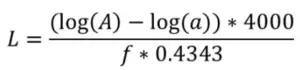
The mouth of the horn determines this length. If you want the mouth to be a certain size, the horn’s neck will be a specific length. The formula for checking the length of the neck when the cross-section area grows exponentially:
- A is an abbreviation for an aria of the mouth (cm2).
- a = tracheobronchial aria (cm2).
- F denotes the lowest frequency.
- L is the length of the neck.
Assume I have an 8″ (20 cm) woofer and want it to go down to 50 Hz.
For argument’s sake, the throat is equivalent to the woofer’s diameter. Therefore, the area is R2 = 3.14 * 102 = 314 cm2.
The diameter of the mouth must be 340 cm in order to achieve 50 Hz. Hence the mouth area will be 3.14 * 1702 = 3.14 * 28900 = 90746 cm2.
f = 50 Hz
And Length=(log(90746) – log(314)) *4000 / (0.4343 * 50) = (4.96 – 2.50) * 4000 / 21.72 = 453 cm.
The front area of the driver may be smaller relative to the driver’s real size. This means that this area will first constrict to give a tiny throat for a better high-frequency response and then gradually expand.
As a result, a high-pressure area is formed. The sealed chamber behind the cone equalizes this pressure, reducing non-linear distortion.
We realized that the size of the horn is directly proportional to the frequencies we wish to play. This means tiny and medium-sized horns for high and mid-frequency frequencies and massive horns for low-frequency frequencies.
It is impractical to construct a horn with a mouth diameter of 3.5 m since it will most likely fit any place. So, for horns that need to go low, below 100 Hz, a folded or coiled design must be used.
Lab Horn Subwoofer Limitations
Lab horns are amazing and great, but they have limitations. Three things fundamentally limit the performance of a lab horn:
Length:
The first Limitation is its length. The low-frequency range of the horn is governed by its length. Therefore its length, from driver to mouth, is multiplied by 4 is the wavelength beyond which it is relatively useless.
A lab horn must be 112.5″ (9.375′) or 2.86m long to be effective at 30Hz.
Here’s why you need the extra space: The internal path length between the driver and the mouth must be sufficient to sustain one-quarter wavelength of the lowest frequency that the horn (or array of horns) is required to reproduce.
If the horn is not long enough, the pressure wave will exit the mouth while the cone is still pressing forward, reducing efficiency and causing the driver to hyperextend.
As a result, a horn must be long enough to support the wave’s expansion to the lowest frequency required.
Assuming that your low-frequency aim is 30 Hz, the horns you select must be AT LEAST 2.85m long.
Constant Flare:
The second constraint is known as the “flare constant.” This is the pace at which the horn’s area grows in relation to its distance from the neck or driver.
In general, the slower the horn flares, the lower the target cut-off frequency (expand).
The combination of a longhorn and a slow flare required to construct a quasi-portable horn with high low-frequency sensitivity and relatively flat response necessitates a large number of folds and a large amount of wood.
This complicates and increases the cost of their construction, as well as makes the boxes heavier and bulkier.
When building a lab horn with a low-frequency flare rate, one must choose between efficiency and size on a scale.
Most lab horns of a decent size are NOT constructed with a low flare constant and a long enough path.
This results in a peaky reaction and “horn honk,” as well as a complete lack of depth in their performance. These are sacrifices I am unwilling to accept.
Radiating Area:
The third constraint is that a horn must have a radiating area with a perimeter that should be at least one full wavelength of the lowest frequency to be replicated.
For 30Hz, the perimeter of the horn array’s frontal area would need to be 37.5 feet. This results in an array that is somewhat more than 6 feet high and 6 feet wide.
(3m in height by 3m in width) Anything less, and the low-frequency response is compromised. Not only are the lowest frequencies lost, but the response tends to become peaky again, removing the smoothness of a flat system.
This information indicates that installing or transporting a lab horn-only subwoofer system with a flat frequency response to 30Hz would require a significant amount of space, numerous cabinets, and a significant amount of money.
But what’s the point? People do not like lab horns because of their low-frequency response. It’s the impact and speed with which they deliver their message. It’s the tightness, punchiness, and incredibly dynamic transient reaction.
As a result, if you utilize the horns for THAT purpose and direct radiators for the extended low-frequency response, you may use smaller horns that are specifically intended for and perfectly suited to producing the impact that people like!
Due to the limitations of low-frequency horn-loading, a single vented box cannot accomplish flat frequency response and low-frequency extension in an acceptable size. However, a single vented box can reproduce extremely low frequencies.
Not as efficiently, but in a smaller, lighter, more cost-effective, and portable enclosure.
With vented boxes, power and power handling become more important issues, yet they can achieve things that horns cannot. It works in both directions. Each is superior to the other in its area of expertise.